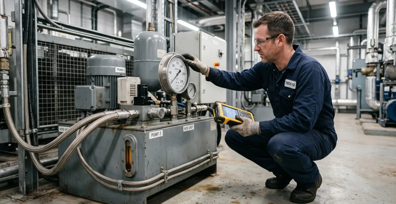
A hydraulic system can deliver adequate pressure on a gauge and still suffer from hose leaks, premature pump wear or overheating. The problem is often not insufficient pump power. It is a mismatch between pressure control, component ratings, fluid cleanliness, cooling capacity and the way equipment operates under load.
For stable hydraulic power, start with measured flow demand and peak pressure, then select a compatible pump, properly rated hose assemblies, suitable relief protection, effective filtration and sufficient heat rejection. An accumulator may help absorb transient pressure shocks, but it cannot compensate for every control or sizing problem.
Domestic water-pressure systems require a related but different approach. Their pressure vessels, switches and variable-speed pumps solve flow and cycling problems rather than the high-pressure force-transmission requirements of industrial oil hydraulics. The distinction matters when diagnosing unreliable pumps or choosing upgrades.
Whether assessing a workshop hydraulic power unit or a household booster pump, the safest approach is to measure the actual operating conditions before replacing components. High-pressure oil systems, charged accumulators and electrical pump controls should be inspected or serviced by suitably competent personnel using the manufacturer’s isolation and depressurisation procedures.
Hydraulic system reliability: the essentials
- Measure real operating and transient pressures before selecting hoses, accumulators or pressure-control components.
- Choose circuit architecture, filtration and cooling around the duty cycle rather than nominal pump capacity alone.
- Diagnose vessel drawdown, leaks and actual flow demand before upgrading a domestic water-pressure pump.
- Why Do Hydraulic Systems Fail After a Sudden Pressure Spike?
- How to Choose Hydraulic Hose Ratings So You Don’t Blow a Line at Peak Load?
- Open-Loop vs Closed-Loop Hydraulics: Which Makes Sense for Continuous Operation?
- The Filtration Mistake That Can Ruin a Hydraulic Pump in 3 Months
- When Should You Change Hydraulic Fluid if the System Runs Daily vs Weekly?
- Pressure Vessel Upgrade or Variable-Speed Pump: Which Fixes Low Pressure Best?
- How to Do a Basic Load Audit Before You Ask for a Supply Upgrade?
- Why Does Your Water Pump Cycle Every 30 Seconds and Add £20 a Month to Bills?
Why Do Hydraulic Systems Fail After a Sudden Pressure Spike?
Hydraulic systems fail after sudden pressure spikes when transient pressure exceeds the capability of a hose, seal, fitting or other component. A rapid valve closure, stalled actuator or abrupt load change can create these peaks. Relief-valve dynamics and inadequate damping may make the event more severe, but identifying the actual trigger is essential before choosing a repair.
A pressure spike is a short-duration increase above the normal operating pressure. It may occur too quickly for a conventional mechanical gauge to display accurately. Consequently, a system that appears to operate safely at its usual pressure can experience damaging peaks during rapid movement or shutdown.
The failure sequence depends on the component exposed. A hose may expand or rupture, a seal may extrude or deform, and an overloaded fitting may start leaking. Repeated transients can also accelerate fatigue even when an immediate rupture does not occur.
Pressure-relief valves protect hydraulic circuits within their design and response limitations. However, their dynamic behaviour, installation location and available discharge capacity affect the protection they provide against fast transients. A relief valve with an incorrect setting can compound the problem; a correctly set valve is not necessarily sufficient to absorb every shock.
Begin diagnosis by identifying the operating event associated with the pressure increase:
- Actuator or motor stall: pressure rises when the driven load stops moving while hydraulic flow continues.
- Rapid valve closure: moving fluid decelerates suddenly, producing a hydraulic shock comparable in principle to water hammer.
- Cold startup: increased oil viscosity can raise flow resistance and pressure losses, particularly where valves or filters are restrictive.
- Rapid load reversal: changing actuator forces may introduce pressure oscillations or localised peaks.
A pressure transducer with sufficient sampling capability can reveal transients that an ordinary gauge misses. Measurements should be taken at relevant circuit locations under controlled conditions by competent personnel, without exposing anyone to a potential hose rupture or injection injury.
An accumulator can provide shock absorption or pulsation damping when its volume, pressure range, pre-charge, flow capability and location are appropriate. HYDAC‘s hydraulic accumulator technical FAQ identifies these operating conditions as important selection factors.
The choice between adding damping hardware and changing the operating sequence depends on the cause. A recurring pressure oscillation may justify an appropriately engineered damping arrangement. If an abrupt control command creates the spike, adjusting valve timing or actuator deceleration may address the source more effectively.
Repeated shock loading can also produce wear particles from damaged components. Those particles increase the contamination burden on the oil and filters, potentially linking a pressure-control problem to accelerated component wear.
Once pressure transients are understood, the next reliability decision is ensuring that every hose assembly is compatible with the actual pressure envelope.
How to Choose Hydraulic Hose Ratings So You Don’t Blow a Line at Peak Load?
Select a hydraulic hose assembly whose specified maximum working pressure is suitable for the highest pressure it can experience, taking account of transients, temperature, compatibility and installation conditions. Check the hose and fitting assembly ratings together. A 4:1 burst-to-working-pressure design factor is common in hydraulic hose standards, but it is not an additional safety multiplier to apply to an already rated hose.
A frequent misunderstanding is to treat burst pressure as usable operating capacity. Burst pressure is associated with qualification and design testing, whereas maximum working pressure is the relevant starting point for selecting a hose.
4:1
A commonly used minimum burst-pressure-to-working-pressure design ratio in hydraulic hose technical standards. It does not permit operation above the hose’s specified working-pressure limit.
For example, an assembly with a declared maximum working pressure must be assessed against the circuit’s actual maximum exposure, rather than assuming that its burst rating provides additional usable operating capacity. If the measured transient exceeds the declared working limit, the installation needs an appropriately rated assembly or a verified reduction in peak pressure.
Pressure capability is not the only selection parameter. Check the manufacturer’s documentation for:
- Maximum working pressure for the specific hose size and complete fitting assembly.
- Fluid compatibility with the inner tube, seals and fittings.
- Permitted operating temperature and any pressure derating requirements.
- Minimum bend radius and restrictions near the crimped ends.
- Impulse-test suitability for repeated pressure cycling.
- Installation requirements for abrasion, movement, twisting and restraint.
Impulse resistance deserves particular attention where a machine cycles frequently. A hose that withstands a steady pressure may perform differently under repeated pressure pulsation. Dynamic bending, vibration and poor support near a crimp can further increase fatigue loading.
Hose failures near fittings may result from multiple interacting causes, including improper assembly, excessive bending, vibration, incompatible components and pressure cycling. A visible crack near a crimp therefore warrants investigation of the entire installation rather than replacement with an identical hose by default.
For verification, use recorded peak pressure from a suitable measurement system, the manufacturer’s assembly specifications and the actual routing geometry. A pump nameplate or relief-valve setting alone does not establish the maximum pressure every hose will experience.
Never inspect a suspected hydraulic leak with bare hands. High-pressure fluid can penetrate skin through a tiny opening and cause a medical emergency. Stop and isolate the equipment, release stored pressure according to the manufacturer, and replace damaged assemblies using approved components and procedures.
Correct hoses contain pressure safely, but continuous operation also requires an architecture that controls heat, replenishes fluid and supports maintenance.
Open-Loop vs Closed-Loop Hydraulics: Which Makes Sense for Continuous Operation?
Open-loop hydraulics are often easier to cool, filter and service because returning oil passes through a reservoir. Closed-loop hydrostatic circuits can offer effective bidirectional drive control, but require careful charge-flow, flushing and heat-management design. For continuous operation, the better choice depends on load behaviour, cooling requirements, pump inlet conditions and maintenance access rather than duty duration alone.
In an open-loop hydraulic transmission circuit, the pump draws fluid from a reservoir and delivers it to the actuator or motor. Fluid then returns to the reservoir, normally through return-line components selected for the system.
In a closed-loop hydrostatic drive, the main pump and hydraulic motor exchange most of their operating flow directly. A separate charge or replenishment circuit typically compensates for leakage and supports cooling and fluid exchange.
Neither arrangement is inherently immune to overheating. Heat generation depends on hydraulic and mechanical losses, while operating temperature depends on how effectively that heat is rejected.
The following comparison focuses on practical engineering trade-offs.
| Decision factor | Open-loop circuit | Closed-loop circuit |
|---|---|---|
| Typical application | Cylinders, mixed actuators and general hydraulic functions | Hydrostatic drives and controlled bidirectional motor operation |
| Cooling arrangement | Reservoir return flow can support cooling and conditioning | Often requires designed flushing, charge flow and heat exchange |
| Reservoir considerations | Typically needs more reservoir-based fluid management | Main circuit recirculates fluid; auxiliary reservoir and charge capacity still matter |
| Filtration access | Return or pressure-line filtration can be relatively accessible | Charge and flushing circuits require carefully selected filtration |
| Continuous moderate load | Suitable with correct pump sizing and thermal management | Suitable when charge, flushing and cooling capacity are adequate |
| Intermittent high-torque drive | Possible, depending on control architecture | Often attractive for reversible hydrostatic drive applications |
| Maintenance considerations | Reservoir conditioning and components may be easier to access | Additional charge and flushing functions increase diagnostic complexity |
Consider a hydraulic motor operating continuously under moderate load. An open-loop arrangement may simplify oil cooling through the reservoir and return circuit. A closed-loop arrangement may be preferable if precise reversible drive control is important, provided the flushing flow and cooler are designed for the expected losses.
A closed-loop drive with an auxiliary open-loop charge and cooling circuit is also a practical architecture. It provides the control characteristics of a hydrostatic drive while allowing heat removal and replenishment through dedicated components.
This additional complexity is worthwhile when it serves a genuine control or packaging requirement. It should not be added merely because closed-loop operation appears more efficient in isolation.
During selection, request a thermal balance covering expected duty cycle, pump and motor losses, cooler capacity and permissible oil temperature. Confirm charge-pump inlet conditions and the manufacturer’s allowable operating limits.
Whichever architecture is selected, reliable operation also depends on keeping abrasive contamination out of the pump’s critical clearances.
The Filtration Mistake That Can Ruin a Hydraulic Pump in 3 Months
The filtration mistake most likely to accelerate hydraulic pump wear is selecting a filter without checking its removal efficiency against the pump manufacturer’s required fluid cleanliness. A filter may be present yet ineffective because its media are unsuitable, its bypass is open or contamination enters elsewhere. Severe wear can develop quickly, but failure within three months is not a universal or predictable outcome.
Hydraulic pump components operate with controlled internal clearances. Solid contaminants can promote abrasive wear, damage sliding surfaces and reduce efficiency. In sensitive components, small particles matter even when the fluid looks visibly clean.
The ISO 4406 cleanliness code expresses particle contamination in hydraulic fluid using three particle-size categories: particles at or above 4, 6 and 14 micrometres, measured using the applicable calibrated counting method.
The acceptable cleanliness target is equipment-specific. For example, Parker’s PV axial piston pump installation documentation identifies ISO 4406 cleanliness class 18/16/13 for applications requiring improved service life and functional reliability. This figure must not be treated as a universal requirement for every hydraulic pump.
Filter selection also involves efficiency at the relevant particle size, often expressed using a beta ratio. A micron label alone does not describe how consistently a filter removes particles under defined test conditions.
A filtration system that performs well when the oil is warm may behave differently at cold startup. High viscosity can increase pressure differential across the element and, depending on the filter assembly, activate a bypass path. Similarly, restrictive suction filtration may impair pump inlet conditions and contribute to cavitation.
Oil sampling helps verify whether filtration achieves the required cleanliness. Sampling from a return line, reservoir or specified pressure-side point can produce different results because each location represents a different part of the fluid circuit. Use defined sampling points and consistent procedures, with the equipment safely configured for sampling.
Parker‘s PV axial piston pump installation manual documents filtration, viscosity and cleanliness requirements for the specified pump family. It also recommends filling through a filtration device, reinforcing the importance of controlling contamination before the equipment starts operating.
Compare laboratory particle counts with the component manufacturer’s cleanliness requirement. If the target is not achieved, investigate filter efficiency, bypass operation, reservoir breathers, maintenance practices and possible internal wear before changing filter media.
Five checks for a documented hydraulic reliability assessment
- Record the pump make, model and manufacturer cleanliness requirement; produce a component specification sheet.
- Review existing filter elements, efficiency information and bypass arrangements; create a filtration inventory.
- Identify approved sampling locations and arrange a representative fluid test; obtain a particle-count report.
- Compare measured cleanliness with the applicable target and inspect relevant maintenance records; prepare a contamination gap assessment.
- Document corrective actions, responsible personnel and follow-up sampling requirements; produce a maintenance action record.
Contamination-driven wear can also reduce volumetric efficiency and increase hydraulic losses. Greater losses may contribute to additional heat generation, while generated wear debris can further increase contamination.
Filtration protects the circulating fluid, but oil quality also changes through heat exposure, moisture, oxidation and operating time. Fluid replacement should therefore follow condition as well as usage.
When Should You Change Hydraulic Fluid if the System Runs Daily vs Weekly?
Change hydraulic fluid according to the manufacturer’s maintenance requirements and its measured condition, not solely because a fixed number of months has passed. Daily operation calls for close attention to operating hours, contamination and thermal stress. Weekly operation still requires periodic checks for moisture, oxidation and deterioration during storage. Neither duty pattern guarantees a particular safe replacement interval.
Hydraulic oil serves several functions beyond transmitting power. It lubricates moving surfaces, assists heat transfer, limits corrosion and provides a medium for contamination removal.
Its performance can deteriorate when viscosity changes, additives become depleted or contamination exceeds acceptable levels.
Daily operation typically makes running hours an important maintenance indicator. Repeated heating, pressure cycling, particle ingress and sustained exposure to operating temperatures can affect fluid condition. Where equipment operates continuously or failure consequences are significant, scheduled laboratory analysis provides stronger evidence than visual inspection alone.
Weekly or occasional operation presents different risks. Equipment may undergo repeated heating and cooling, allowing moisture-related problems where the reservoir is exposed to humid air. Long idle periods do not prevent oxidation, water ingress or contamination from occurring.
For either operating pattern, relevant measurements may include viscosity, particle count, water content and acid number, interpreted against the original fluid specification and historical trends.
| Assessment | Daily operation | Weekly operation |
|---|---|---|
| Primary monitoring basis | Operating hours and condition trends | Condition, storage environment and elapsed time |
| Common concerns | Heat exposure, wear particles and contamination | Moisture ingress, oxidation and idle-period contamination |
| Routine observations | Temperature, appearance, filter indications and unusual behaviour | Appearance, condensation indicators and condition before use |
| Laboratory testing | Interval based on duty severity and equipment criticality | Interval based on manufacturer guidance, environment and condition trends |
| Replacement decision | Specification limits, results and maintenance requirements | Specification limits, results and maintenance requirements |
A simple visual check can reveal cloudiness, unusual darkening or free water. A blotter spot test may provide a preliminary indication of some contamination or degradation patterns, but its interpretation depends on fluid type and test method. Neither check establishes that the oil is chemically sound or sufficiently clean.
When laboratory testing is introduced, establish an initial baseline and define a review interval suited to operating severity. The interval can then be adjusted using manufacturer recommendations and observed trends rather than adopting a universal run-hour threshold.
Changing oil does not automatically restore system cleanliness. Contaminated reservoirs, dirty filling equipment and retained debris can immediately compromise the replacement fluid. Where a failure has occurred, additional cleaning or flushing may be required under an approved maintenance procedure.
Always verify that the replacement fluid has the correct viscosity and material compatibility for the equipment. Mixing products without approval can create additional performance problems.
For domestic water-pressure systems, the reliability question moves away from hydraulic oil maintenance and towards pump output, pressure storage and demand management.
Pressure Vessel Upgrade or Variable-Speed Pump: Which Fixes Low Pressure Best?
A larger pressure vessel is generally the appropriate upgrade when an otherwise adequate water pump starts too frequently because insufficient usable water is stored between its pressure settings. A variable-speed pump can improve pressure regulation under changing demand, provided the pump can deliver the required flow and head. Neither option solves a fundamentally inadequate water supply, blocked pipe or unresolved leak.
Although both components influence household pressure behaviour, they perform different functions.
A pressure vessel stores a usable volume of pressurised water. In systems using a conventional pressure switch, this stored volume allows some demand to be supplied before the pump restarts.
Increasing usable drawdown may reduce start frequency when vessel capacity is the limiting factor. It does not increase the pump’s maximum continuous flow capability.
A variable-speed pump adjusts motor speed in response to demand and control feedback. A properly designed system can maintain more consistent pressure over part of its operating range than a simple fixed-speed arrangement.
However, a variable-speed drive cannot create unlimited pump capacity. At high demand, the pump still operates within its available performance envelope. Low inlet pressure, insufficient source flow, undersized pipework or restrictions can remain decisive limitations.
The US Department of Energy pumping system performance sourcebook explains how adjustable-speed drives can match pump output to changing demand. It also highlights why whole-system assessment matters before modifying equipment, although its guidance principally addresses industrial pumping applications.
A useful comparison separates the symptoms and maintenance consequences.
| Consideration | Larger pressure vessel | Variable-speed pump |
|---|---|---|
| Main benefit | More usable stored water between starts | Speed adjustment to changing demand |
| Frequent on/off cycling | Can reduce starts if drawdown is inadequate | Can change cycling behaviour when correctly configured |
| Insufficient peak flow | Does not improve sustained pump capacity | May help only if pump and motor have sufficient available capacity |
| Typical maintenance | Pre-charge, bladder and vessel inspection | Pump, sensors, controller and electrical checks |
| Main limitations | Space, finite drawdown and potential air or bladder faults | Electronics, cooling, power quality and control compatibility |
Diagnose the problem by observing pressure during demand, pump runtime, restart frequency and pressure recovery. If pressure is satisfactory while running but the pump starts repeatedly during small drawdowns, investigate the vessel and controls first.
If pressure drops when several outlets are used simultaneously and the pump cannot maintain the required flow, compare the actual demand with the pump performance curve. A suitably specified variable-speed unit may help, but a different pump or correction of system restrictions may be necessary.
Where demand is both variable and substantial, a correctly sized vessel and variable-speed pump may work together. Vessel selection then depends on the drive’s control strategy, minimum flow requirements and the manufacturer’s recommendations.
Safety matters here too. A domestic pressure vessel must be rated and approved for the intended water service, and its inspection and maintenance should follow the manufacturer’s instructions. Vessel pre-charge adjustments require the proper electrical and hydraulic isolation procedures.
Before purchasing either upgrade, an assessment of simultaneous water demand and existing supply capacity can prevent unnecessary expenditure.
How to Do a Basic Load Audit Before You Ask for a Supply Upgrade?
A basic load audit identifies what the system must supply, when that demand occurs and whether the existing equipment can meet it. Record individual loads, estimate realistic simultaneous use, measure pressure and flow during demanding conditions, and compare the results with installed capacity. The objective is to document a genuine shortfall rather than sizing new equipment from nameplate ratings alone.
For a household water system, start by listing outlets and appliances that may operate together. For a hydraulic power unit, identify actuators, motors, operating pressures and sequences that determine simultaneous flow and power requirements.
These systems should not be combined into a single calculation: domestic booster systems are assessed through water flow and head, while hydraulic transmission systems also require force, torque, pressure and hydraulic power evaluation.
A practical audit can follow this sequence:
- List demand points. Identify connected equipment, its function and relevant operating characteristics.
- Record normal operation. Note when each load operates and whether demands are continuous, intermittent or occasional.
- Identify simultaneity. Separate loads that genuinely run together from loads that operate at different times.
- Measure difficult conditions. Record relevant flow, pressure and runtime data during periods of high demand.
- Compare available capacity. Use actual system measurements and manufacturer performance information to identify the limiting component.
Peak requirement should not automatically be calculated by adding every installed nameplate value. A group of pumps, outlets or actuators may rarely operate simultaneously. Equally, measuring only a quiet operating period can underestimate the highest real demand.
Where possible, use logged data covering representative operating periods, including the busiest expected conditions. Note measurement locations and instrument limitations so a supplier can interpret the findings.
Waste and malfunction should be considered before increasing supply capacity. Leaks, repeated short cycling, excessive throttling and poorly matched equipment can produce symptoms resembling inadequate supply.
The scale of the loss must be measured rather than assumed. A small leak may be insignificant relative to peak flow in one installation but materially affect cycling in another.
Prepare a one-page audit summary with the following information:
| Audit field | Information to document | Purpose |
|---|---|---|
| Demand points | Equipment or outlet list | Defines connected loads |
| Peak demand | Measured or justified simultaneous requirement | Establishes design conditions |
| Duty profile | Operating duration and frequency | Supports equipment and cooling selection |
| Existing capacity | Pump curve, installed controls and relevant ratings | Defines available performance |
| Measured shortfall | Pressure, flow or performance deficit under load | Identifies the problem to solve |
| Known losses | Leaks, restrictions or cycling abnormalities | Separates maintenance faults from capacity issues |
This document enables an installer or supplier to recommend equipment against an identified operating requirement. It also provides a useful baseline for checking whether the completed upgrade has actually improved performance.
For electrical supply upgrades associated with pumps, include measured motor demand, starting characteristics and appropriate electrical assessments. Such work should be reviewed by a qualified electrician rather than inferred solely from hydraulic or water-flow measurements.
The same diagnostic discipline is especially valuable when a domestic water pump keeps restarting despite little apparent demand.
Key takeaways before troubleshooting a cycling pump
- Pressure storage and pump capacity solve different problems: establish whether the symptom is frequent starting or inadequate sustained flow.
- A load audit should capture high-demand conditions while separating genuine capacity shortfalls from leaks and control faults.
- Investigate vessel condition and the pressure-control system before treating an equipment upgrade as necessary.
Why Does Your Water Pump Cycle Every 30 Seconds and Add £20 a Month to Bills?
A water pump restarting every 30 seconds may be short cycling because of inadequate pressure-vessel drawdown, an incorrect pre-charge, a leak, a faulty check valve or unsuitable pressure-switch settings. Frequent starts can increase wear and some energy losses, but they do not automatically add £20 per month. The actual cost depends on pump power, operating behaviour and electricity charges.
The first distinction is between normal operation under active water demand and unexpected restarting when outlets are closed.
If water is being drawn continuously, pump cycling may reflect the vessel’s available drawdown, the switching pressure range and actual flow demand. If the pump restarts repeatedly with all outlets closed, investigate pressure loss, leakage and control behaviour.
A pressure vessel contains an air or gas cushion separated from the water by a diaphragm or bladder in many designs. As water is discharged, system pressure falls until the pump reaches its cut-in pressure. The pump then refills the vessel and restores pressure to the cut-out setting.
Insufficient usable drawdown reduces the time between pump starts. This can result from an undersized vessel, incorrect pre-charge or a failed internal diaphragm or bladder.
Other possible causes include a leaking outlet, an unnoticed pipe leak, reverse flow through a defective check valve or a pressure switch with an unsuitable operating differential.
Observe the system without changing electrical settings or opening pressurised components. A useful first diagnostic record includes pump start and stop times, pressure at each event and whether water was being used.
Checking the vessel pre-charge against the manufacturer’s requirement is a useful early diagnostic step. An accurate air-side measurement generally requires the vessel’s water side to be isolated and depressurised using the prescribed procedure. A reading taken while the vessel remains under water pressure may not reveal the true pre-charge condition.
A technician can then determine whether the vessel has lost air, its bladder has failed or its storage capacity is inappropriate. The check valve and switching controls should be assessed before purchasing a replacement pump.
Frequent motor starting does not automatically imply a fixed electricity penalty. Starting current may be substantially higher than running current, but the associated energy use depends on the start duration and motor characteristics. Repeated starts can also create additional heating and mechanical or electrical stress.
To estimate the electricity cost, distinguish energy used during normal pumping from the incremental energy attributable to the cycling fault.
For a clearly hypothetical calculation, suppose a pump draws 1 kW while running and a fault causes an additional 15 minutes of actual running each day. At an assumed electricity price of £0.25 per kWh, the additional running energy would cost approximately £1.88 over 30 days:
1 kW × 0.25 hours/day × 30 days × £0.25/kWh = £1.875.
This illustrative calculation does not quantify startup losses or establish the cost of a real short-cycling installation. A measured electrical power profile, including runtime and starts, is needed to estimate the difference reliably.
Moreover, reducing pump starts does not necessarily reduce energy consumption by a proportional amount. A vessel may change when water is pumped without materially changing the total amount of water delivered. Any energy savings depend on system efficiency, operating pressure and control behaviour.
The corrective sequence is therefore straightforward: confirm whether demand exists, document the cycling pattern, inspect vessel condition and pre-charge, investigate leakage or backflow, and verify pressure-control operation. Only then assess whether a larger vessel or variable-speed pump is warranted.
Record several complete pump cycles and the corresponding pressure readings, then give those observations and the equipment model details to a qualified pump installer. A diagnosis based on those measurements is a safer starting point than replacing components solely because the pump restarts frequently.
Can a hydraulic system leak even when its normal pressure is below the hose rating?
Yes. Transient pressure peaks, poor hose routing, damaged seals, incompatible materials, vibration or defective fittings can cause leakage even when a normal gauge reading is within the stated working-pressure limit. Check the complete assembly and relevant operating conditions. Never use hands to locate a suspected high-pressure oil leak.
Does installing an accumulator eliminate the need for a pressure-relief valve?
No. An accumulator can store hydraulic energy and absorb certain pressure fluctuations, but it is not a general substitute for correctly designed overpressure protection. Accumulators also retain stored energy after a pump stops and require appropriate isolation, discharge and servicing arrangements.
Can hydraulic oil be reused if it looks clean?
Visual appearance alone cannot confirm acceptable viscosity, additive condition, water content or particle cleanliness. Continued use should be based on the equipment manufacturer’s requirements and, where appropriate, representative laboratory analysis. Clear-looking oil can still contain damaging particles or dissolved contaminants.
Will a bigger water-pressure vessel increase shower pressure?
Not necessarily. A larger vessel increases potential stored drawdown within the designed pressure range but does not raise the pump’s sustained flow or head capability. If shower pressure falls during continuous demand, investigate available pump performance, pipework restrictions, supply conditions and simultaneous water use.
What measurements should a pump installer receive before recommending an upgrade?
Useful information includes the existing pump model and performance curve, pressure readings under low and high demand, measured flow where available, start and stop frequency, vessel specifications, known leaks and the desired operating conditions. For oil-hydraulic equipment, add transient pressure, duty cycle, fluid temperature and relevant component ratings. Measurements should be gathered using safe, appropriate methods.