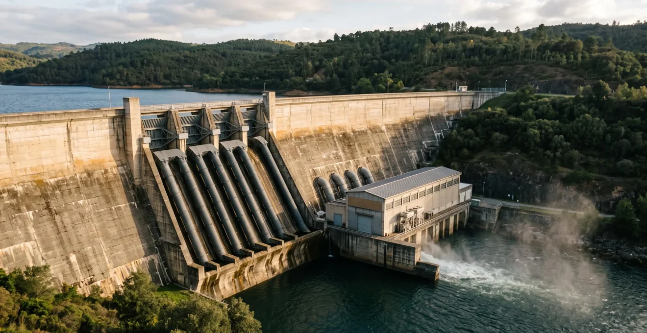
Hydroelectricity generates electricity by converting the energy of water moving from a higher elevation to a lower one. The water passes through a turbine, makes it rotate, and continues downstream. What the power station extracts is energy, not the water itself.
Imagine a heavy object resting on a high shelf. Its position gives it potential energy, which can be released as it falls. Water stored behind a dam follows the same principle. A controlled descent through a pipe drives a turbine connected to an electrical generator. The generator converts mechanical rotation into electricity through electromagnetic induction.
The important distinction is that water is the carrier of energy, not a fuel that disappears during generation. The water remains in the river system, although dams and reservoirs can change its timing, temperature and environmental conditions. Evaporation and other water losses can also occur.
Understanding this distinction makes it easier to compare hydroelectric sites, assess turbine efficiency, recognise water-supply constraints and understand why pumped hydro can store electricity for later use.
Hydroelectricity in three essential points
- Height and flow determine available power: greater hydraulic head provides more energy per cubic metre, while greater flow supplies more cubic metres each second.
- Generation does not consume water as fuel: the turbine extracts hydraulic energy, and the water continues through the system, subject to operational and environmental constraints.
- Stored water provides flexibility: reservoirs can shift generation to periods of demand, while pumped hydro uses electricity to lift water for later energy recovery.
- Why Is Water Height More Important Than Flow Speed in Many Hydro Setups?
- How to Map Where the 10–20% Energy Loss Happens in a Hydro System?
- Pelton vs Kaplan Turbines: Which Fits High-Head vs Low-Head Water Sites?
- The “Perpetual Power” Myth That Makes Hydroelectricity Sound Like Magic
- When Does a Hydroelectric Plant Have to Spill Water Instead of Generating Power?
- Why Does Water Flow Create a Higher Capacity Factor Than Sun or Wind?
- How to Estimate Stored MWh From Water Volume and Height Without Heavy Maths?
- Why Is Pumped Hydro Still One of the Cheapest Ways to Store Energy for 8–12 Hours?
Why Is Water Height More Important Than Flow Speed in Many Hydro Setups?
Water height matters because the vertical drop, called hydraulic head, determines how much gravitational potential energy each kilogram of water can release. Flow speed often results from converting that potential energy into movement. For a hydroelectric site, measuring elevation difference and usable water flow is generally more informative than measuring the apparent speed of the river surface.
A reservoir high above a powerhouse contains gravitational potential energy. When water enters a penstock, the large pipe directing it towards the turbine, some of that energy becomes pressure and motion. The turbine extracts energy from the moving and pressurised water, and the generator turns the resulting shaft rotation into electricity.
The relationship between hydraulic power, head and flow can be written as:
Hydraulic power = water density × gravitational acceleration × flow rate × head.
In engineering notation, this is P = ρgQH. To estimate electrical output, multiply the hydraulic power by the combined efficiency of the installation.
At an unchanged flow rate, doubling the usable head doubles the theoretical hydraulic power. Doubling the flow at unchanged head produces the same proportional increase. Head is therefore not universally more important than flow; the two quantities work together.
Consider two hypothetical sites delivering the same water volume each second. One offers a 10-metre drop, while the other offers 100 metres. Before accounting for losses, every cubic metre at the second site carries ten times the gravitational energy available at the first.
The distinction also explains why a fast-moving river is not automatically an excellent conventional hydropower site. Surface velocity reveals little about the total usable head, the volume that can be diverted, or the pressure available at a turbine. Free-flow kinetic-energy turbines are a different category and depend more directly on current speed.
Low-head generation remains possible. However, delivering the same power from a smaller drop requires a correspondingly greater water flow, before efficiency differences are considered.
The U.S. Department of Energy explanation of how hydropower works identifies both head and flow as the fundamental determinants of available hydropower.
Once the theoretical energy available from the water is understood, the next question is how much of it survives the journey through pipes, machinery and electrical equipment.
How to Map Where the 10–20% Energy Loss Happens in a Hydro System?
Energy losses in a hydroelectric system can be traced from the reservoir to the grid connection. Water encounters friction in the penstock, the turbine converts hydraulic energy imperfectly, and the generator and electrical equipment introduce further losses. A total loss of 10–20% can serve as a broad illustrative range, but it is not a universal specification for every installation.
A useful approach is to follow the energy through each conversion stage rather than assigning a single unexplained efficiency figure to the whole plant.
| Stage | What happens | What to examine |
|---|---|---|
| Intake and penstock | Friction, bends, valves and restrictions reduce usable hydraulic head. | Pipe length, internal diameter, roughness and flow rate. |
| Turbine | Some hydraulic energy remains in the exiting water or is dissipated by turbulence and mechanical losses. | Turbine type, operating point and efficiency curve. |
| Generator | Electrical resistance, magnetic effects and mechanical friction produce losses. | Generator efficiency and operating load. |
| Transformer and cables | Electrical energy is lost as heat during voltage conversion and transmission. | Electrical equipment efficiency and cable losses. |
The most easily overlooked component in a small hydro installation may be the penstock. A long, narrow pipe can consume a substantial portion of the available head through friction. Increasing pipe diameter can reduce this loss, although the larger pipe may cost more to install.
Engineers distinguish gross head, the elevation difference between upstream and downstream water levels, from net head, the hydraulic head available to the turbine after relevant hydraulic losses.
For example, consider a purely hypothetical site with 100 metres of gross head and 5 metres of hydraulic head loss. Its net head is 95 metres. At the same flow, the hydraulic energy available at the turbine is 95% of the ideal gross-head value, before turbine and electrical losses.
That 5% hydraulic reduction must not be confused with the complete plant efficiency. The remaining equipment introduces additional losses, and efficiencies must be combined across stages rather than simply assuming that every plant loses 10–20%.
A useful way to assess a project is to ask for gross head, calculated or measured head loss at the intended flow, turbine efficiency at that flow, generator efficiency and the electrical delivery point used for the quoted output.
Reducing pipe friction may sometimes be more valuable than selecting a marginally more efficient turbine. Nevertheless, turbine choice remains critical because different head and flow conditions require different mechanical designs.
Pelton vs Kaplan Turbines: Which Fits High-Head vs Low-Head Water Sites?
Pelton turbines are generally suited to high-head sites with relatively modest water flow, while Kaplan turbines suit low-head installations carrying larger water volumes. Francis turbines commonly occupy the intermediate range. The correct choice depends on the site’s actual head, design flow, operating variability and installation conditions, not on a turbine’s headline efficiency alone.
The distinction follows the two principal turbine families: impulse and reaction machines.
A Pelton turbine is an impulse design. Water is accelerated through one or more nozzles into powerful jets that strike the runner’s distinctive split, spoon-shaped buckets. The change in water momentum transfers energy to the wheel, which operates in an air-filled housing rather than as a fully submerged reaction runner.
A Kaplan turbine resembles a ship’s propeller. Water flows through its submerged runner, where pressure changes and water motion drive the blades. Adjustable runner blades and guide vanes allow many Kaplan designs to accommodate changing flow conditions.
Francis turbines also operate as reaction machines. They provide another solution where the site’s head and discharge fall between the typical operating regions of Pelton and Kaplan designs.
These broad characteristics provide an initial comparison:
| Criterion | Pelton | Kaplan | Francis |
|---|---|---|---|
| Typical head | High | Low | Intermediate, with overlapping ranges |
| Typical flow | Relatively low | Relatively high | Varies with design |
| Operating principle | Impulse from water jets | Submerged reaction runner | Submerged reaction runner |
| Distinctive feature | Bucket-shaped runner | Propeller-like adjustable blades | Curved runner passages |
| Site assessment | Jet quality and nozzle conditions | Flow passage and submerged equipment | Operating range and hydraulic conditions |
These are selection tendencies, not rigid boundaries. Final turbine sizing also depends on the required output, runner speed, installation depth, cavitation risk and expected operation away from the design point.
The Department of Energy overview of hydropower turbine types confirms the importance of head and flow while also identifying installation conditions, efficiency and cost as selection factors.
Maintenance conditions introduce another important consideration. Low-head installations may admit substantial quantities of sediment, vegetation and floating debris. These materials can obstruct screens, abrade hydraulic surfaces or increase cleaning requirements.
High-head Pelton sites can also experience severe abrasive wear, particularly when sediment passes through nozzles and strikes buckets at high velocity. Therefore, no turbine family should automatically be considered immune to sediment damage.
The practical comparison should include intake screening, sediment management, access for maintenance, expected wear and the local availability of replacement components.
Matching the machine to the site improves the prospects for efficient generation, but even a perfectly selected turbine cannot produce electricity without an available supply of water and usable hydraulic energy.
The “Perpetual Power” Myth That Makes Hydroelectricity Sound Like Magic
Hydroelectricity is not perpetual power. Water can remain available after passing through a turbine, but the energy extracted from its descent cannot be recovered without an additional energy source. Rainfall and the wider water cycle replenish elevated water supplies, while drought, changing river flows and reservoir operating limits determine how much electricity a plant can actually generate.
The misconception begins with a true observation: after water has passed through the turbine, it still exists. Unlike coal or natural gas, it has not been chemically consumed to release energy.
However, water exiting the powerhouse at a lower elevation has surrendered part of the gravitational energy it possessed upstream. Sending that same water back uphill requires energy from somewhere else.
Nature performs much of this lifting through the solar-powered water cycle. Solar heating drives evaporation, moisture enters the atmosphere, and precipitation returns water to higher ground. Snow accumulation and seasonal melting can also determine when water reaches rivers and reservoirs.
This creates an important dependency chain:
- Rainfall and snowmelt influence the water entering the catchment.
- Evaporation, soil conditions and upstream water withdrawals affect how much reaches the reservoir or river.
- Reservoir storage influences how generation can be distributed over time.
- Environmental releases, competing water uses and operating restrictions limit how much can pass through turbines.
A reservoir may provide excellent short-term control while remaining exposed to prolonged drought. In a dry period, operators may need to conserve stored water, reduce electricity production or prioritise other water obligations.
Run-of-river plants face an additional limitation: without substantial storage, their available generating power closely follows the river’s current flow.
Hydropower’s real advantage is therefore not unlimited energy. It is the ability of many installations, particularly those with reservoirs, to change output rapidly when sufficient water and operating head are available.
That controllability is valuable for balancing electricity networks where demand and variable renewable generation change throughout the day.
A plant can preserve the water while extracting energy from it, but available flow and reservoir capacity remain finite. Those limits become especially visible when operators must release water without generating electricity.
When Does a Hydroelectric Plant Have to Spill Water Instead of Generating Power?
A hydropower plant may have to release water without generating electricity when incoming flows exceed turbine capacity, reservoir levels approach safety limits, equipment is unavailable or operating conditions make generation undesirable. Water releases may also be required for environmental purposes. The distinction is between managing water safely and economically, and converting its available hydraulic energy into electricity.
A spillway provides a controlled route for water to bypass the turbines. It can prevent a reservoir from rising beyond safe operating levels, particularly during unusually large inflows.
Dam safety releases take priority over electricity production. If incoming water cannot be safely retained or processed by the generating units, an appropriate release is necessary even when the water could otherwise have generated electricity.
Several operational circumstances can result in water bypassing generation:
- High inflows: floodwater may exceed the combined capacity of the turbines and available reservoir storage.
- Reservoir operating limits: water may need to be released to maintain an appropriate level or flood-control margin.
- Maintenance or equipment faults: unavailable generating units may leave operators unable to process the necessary flow.
- Electricity-market conditions: when generation has little or negative economic value, operators may prefer not to generate if water-management rules permit it.
- Environmental obligations: required downstream flows or routes for aquatic ecosystems may need to be maintained independently of electricity demand.
These circumstances should not be treated as equivalent. A safety spill is a physical and operational necessity. Economic spilling is a decision constrained by reservoir capacity, future electricity value, environmental requirements and other operating rules.
Environmental releases also need careful interpretation. Some required flows can pass through turbines, while others may need to bypass them. A required release is therefore not automatically equivalent to spilled water or lost generation.
The Department of Energy overview of hydropower plant types explains how reservoir releases can serve electricity demand, flood control, recreation, fish passage and other environmental needs.
Spilled water is not destroyed. It continues downstream, but much of the hydraulic energy that might have been captured by the plant is no longer available for electricity generation at that location.
Spillage also illustrates why the amount of water arriving at a dam cannot be treated as the amount that will necessarily pass through its turbines.
For realistic forecasts, turbine capacity must be considered alongside seasonal inflows, reservoir restrictions and the ability to schedule generation. These factors strongly influence how frequently a plant actually operates.
Why Does Water Flow Create a Higher Capacity Factor Than Sun or Wind?
Hydropower can achieve a relatively high capacity factor when reliable inflows and suitable storage allow substantial generation throughout the year. Unlike solar panels, which depend on daylight, a reservoir plant can store water and choose when to release it. However, hydro does not automatically outperform wind or solar: actual capacity factors depend on hydrology, plant design and operating priorities.
Capacity factor compares the electricity actually generated over a period with the amount a plant would produce if it operated at rated power throughout that period.
For example, a hypothetical 10 MW plant operating at its full rated output continuously for 24 hours would produce 240 MWh. If it actually generated 120 MWh, its capacity factor for that day would be 50%.
Capacity factor describes utilisation, not the efficiency of converting water energy into electricity. A technically efficient turbine can belong to a plant with a low capacity factor if insufficient water is available or the operator deliberately preserves it for later.
The main differences between renewable generation technologies concern when their energy inputs are available and how much control operators have over electricity output.
| Technology | Main source of variability | Ability to shift generation |
|---|---|---|
| Solar PV | Daylight, seasons and cloud cover | Limited without separate storage |
| Wind | Weather patterns and wind conditions | Limited without separate storage |
| Reservoir hydro | Catchment inflows and stored water availability | Can shift generation within reservoir and operational limits |
| Run-of-river hydro | River discharge and seasonal hydrology | Limited when substantial storage is absent |
A storage reservoir acts as an energy buffer. Water arriving during a wet period can sometimes be retained and released later, subject to reservoir capacity, water availability and operational constraints.
This can smooth fluctuations in electricity supply, but it does not create more gravitational energy. Generating during a high-demand hour may mean generating less during another hour.
Reservoir plants may also operate with deliberately moderate capacity factors because their installed turbines are designed to deliver substantial output over shorter periods. Such a plant may provide valuable flexibility without producing electricity continuously.
Conversely, a run-of-river facility with dependable year-round flow may achieve a high capacity factor even though it has little control over the timing of generation.
It is therefore misleading to assign a single capacity-factor advantage to all hydropower installations. Comparisons should use the same reporting period and account for water availability, operating restrictions and the intended role of each plant.
Capacity factor helps explain annual generation, but estimating how much energy a reservoir can hold requires a different quantity: the usable water volume multiplied by the effective vertical drop.
How to Estimate Stored MWh From Water Volume and Height Without Heavy Maths?
To estimate the electricity available from stored water, multiply the usable water volume by the effective hydraulic head and an assumed generation efficiency. The result follows directly from gravitational potential energy. A convenient calculation converts cubic metres and metres of head into megawatt-hours, making it possible to compare reservoir options without detailed turbine modelling.
The underlying physical relationship is gravitational energy = mass × gravitational acceleration × height. For a basic estimate using freshwater, one cubic metre has a mass of approximately 1,000 kilograms.
With water density approximated as 1,000 kg/m³ and gravitational acceleration as 9.81 m/s², the calculation becomes:
Electrical energy (MWh) ≈ water volume (m³) × head (m) × 0.000002725 × generation efficiency.
Here, generation efficiency is expressed as a decimal. For example, 85% is entered as 0.85. The coefficient converts the gravitational energy into MWh using these standard physical approximations.
Worked example: a hypothetical hydro storage reservoir
Assume a reservoir has 1,000,000 m³ of usable water, an effective head of 100 metres and an assumed generation efficiency of 85%. These are illustrative inputs, not measurements from an existing facility.
Estimated electricity = 1,000,000 × 100 × 0.000002725 × 0.85 = approximately 232 MWh.
For comparison, the theoretical gravitational energy before generation losses is approximately 273 MWh. The difference represents the assumed losses incorporated into the example.
This can also be expressed as a reusable benchmark: one million cubic metres of water descending through 100 metres contains approximately 273 MWh of theoretical gravitational energy before conversion losses.
However, a real reservoir usually does not maintain a constant head while emptying. As the water level falls, the elevation difference and available energy may change. A more accurate calculation divides the usable storage range into intervals or integrates the changing head over the released volume.
Another common mistake is substituting total reservoir volume for usable volume. Some water may need to remain in storage because of minimum operating levels, environmental requirements, sediment management or other constraints.
Five checks for a defensible hydropower energy estimate
- Record the usable water volume: identify the water available between permitted operating levels and produce a volume figure in cubic metres.
- Establish the vertical drop: record upstream and downstream elevations and produce a gross-head estimate in metres.
- Account for hydraulic losses: identify the expected net head or document the assumed penstock head loss and produce an adjusted head estimate.
- Apply an explicit efficiency assumption: record the combined generation efficiency used in the calculation and produce an estimate in MWh.
- Check uncertainty: repeat the estimate with plausible variations in usable volume, head and efficiency, producing a range rather than one unexplained figure.
The resulting number describes an approximate quantity of electricity, not how quickly the plant can deliver it. A reservoir may contain hundreds of MWh but require several hours to release them through a turbine with limited MW capacity.
This distinction between power and energy is essential: MW describes the rate of generation, while MWh describes the quantity delivered over time.
Once stored MWh and generating MW are estimated separately, it becomes possible to assess whether a reservoir can support short bursts of high output or sustained electricity supply over many hours.
Key considerations before evaluating long-duration storage
- A high reservoir is valuable only when sufficient usable water volume and operating head are available.
- Stored MWh determines energy capacity; turbine MW determines how quickly that energy can be delivered.
- The economic value of storage depends on efficiency, operating flexibility, construction costs and how frequently the stored energy is used.
Why Is Pumped Hydro Still One of the Cheapest Ways to Store Energy for 8–12 Hours?
Pumped hydro can be a cost-effective option for storing electricity over eight to twelve hours because it uses reservoirs, elevation difference and conventional electromechanical equipment rather than purchasing an additional chemical storage medium for every extra unit of energy capacity. Its competitiveness depends on site conditions, construction costs and utilisation, however; it is not universally the cheapest storage technology.
A pumped-storage plant normally uses two reservoirs at different elevations. During charging, pumps move water from the lower reservoir to the upper reservoir using electricity. During discharge, water returns downhill through turbines, generating electricity.
The system behaves like a rechargeable battery, with the difference that its energy is stored primarily as gravitational potential energy rather than through chemical reactions.
The economic attraction is the separation between storage capacity and generating capacity. Larger reservoirs can increase the energy held by a project, while turbines, pumps and electrical equipment determine its charging and discharging power.
Reservoir enlargement is not free: excavation, dam construction, land, environmental measures and infrastructure can be substantial expenses. Nevertheless, suitable geology and topography can make additional storage capacity economical over a long operating life.
Battery storage is also modular and can be highly competitive, particularly where rapid deployment, limited space or shorter discharge duration matters. Increasing battery-system energy capacity generally requires more storage cells, along with associated infrastructure and integration costs.
Long-duration comparisons therefore require a project-specific assessment of total installed cost, discharge duration, lifetime, efficiency and cycling behaviour, rather than a simple claim that one technology is always cheaper.
Importantly, pumped hydro does not recover every unit of electricity used during pumping.
70–80%
Approximate pumped-storage round-trip efficiency reported by the U.S. Department of Energy. This describes the electricity recovered compared with electricity used for pumping, not the efficiency of conventional hydropower generation.
U.S. Department of Energy, 10 Reasons to Love Water Batteries.
At a 70–80 % round-trip efficiency, a hypothetical charging input of 100 MWh would return approximately 70–80 MWh of electricity. The remaining energy is lost through pumping, hydraulic, turbine and electrical conversion processes.
This figure is supported by the Department of Energy article on pumped-storage water batteries. It should not be confused with the efficiency of an ordinary hydro plant that generates electricity from naturally elevated water.
Charging losses mean that pumped hydro is economically useful only when the value of recovered electricity and associated grid services justifies both the energy lost and the cost of the infrastructure.
A site with suitable elevation differences and existing reservoirs may be attractive. A project requiring major excavation, extensive new dams or costly transmission connections may be considerably less competitive.
In the UK, for example, promising pumped-storage locations must be evaluated against terrain, reservoir design, environmental impacts, grid connections and planning requirements. The existence of hills or former quarries alone does not establish project viability.
Long construction timelines and upfront financing requirements also distinguish large pumped-storage developments from modular battery projects that may be easier to deploy incrementally.
A meaningful comparison should examine the cost per usable MWh, discharge power, achievable duration, round-trip efficiency, project lifetime, expected annual cycling and site-specific constraints. Without those inputs, any universal lowest-cost ranking for eight to twelve hours would be unsupported.
What makes pumped hydro enduringly useful is that it can store substantial quantities of energy, release them when needed and reuse much of its physical infrastructure over repeated operating cycles, provided that water-management and engineering conditions remain suitable.
For a practical first comparison, calculate the usable MWh and required MW, determine the desired discharge duration, and then compare site-specific pumped-hydro costs with battery or other storage alternatives. That sequence is more reliable than choosing a storage technology from its advertised efficiency or nominal duration alone.
Does water leave a hydroelectric dam with less energy than it entered?
Yes. Water leaving a turbine has transferred part of its available hydraulic energy to the machinery. It normally exits at a lower elevation or with reduced usable hydraulic energy. The water itself remains, but the energy extracted at that location cannot be recovered without another source of energy.
Can hydroelectricity work without a large dam?
Yes. Run-of-river and diversion installations can use natural elevation differences and channel water towards turbines without requiring a large storage reservoir. Their generating output is often more dependent on immediate river flow, and they still require appropriate hydraulic design and environmental safeguards.
Can a small stream generate useful electricity for a home?
Potentially. Small-scale hydro viability depends on measurable head, reliable flow, hydraulic and electrical losses, installation cost and the applicable permissions. A small stream with substantial head may be more promising than a wider, faster-looking stream with very little usable drop. A site assessment is needed before estimating reliable output.
Why do hydroelectric plants still need the electricity grid?
Grid-connected hydro plants use the electricity network to deliver generated power to consumers and other facilities. The grid also helps operators coordinate output with system demand. A suitably designed standalone hydro installation can supply local electrical loads without a national grid connection, but it needs appropriate control, protection and demand management.
Does pumped hydro need a constant supply of new water?
Not necessarily. A closed-loop pumped-storage system repeatedly transfers water between two reservoirs, although evaporation, seepage and operational requirements may create a need for replenishment. Open-loop systems interact with natural waterways and face additional flow and environmental considerations. Water is circulated to store energy, not consumed as an electrical fuel.